Recovery of wasted cold energy by TEG
The worldwide energy crisis has made people realize the importance of the waste energy recovery, and waste heat recovery has become a popular topic of discussion. However, waste cold is also common. For instance, liquefied gas storage is necessary for hospitals, the natural gas industry, the semiconductor industry, etc. In cryogenic engineering, liquid nitrogen is widely employed in the food, biotechnology, electronics and semiconductor manufacturing, and healthcare sectors, among others. Cold sources have much lower temperatures than the ambient environment. This large temperature difference represents the considerable potential of thermoelectric generator (TEG) applications. In addition, the Carnot cycle efficiency indicates that the lower temperature of the cold reservoir is, the higher the thermal efficiency is.
At the National Synchrotron Radiation Research Center (NSRRC), Taiwan, liquid nitrogen is used to cool the thermal shielding layer of the superconducting niobium cavity and superconducting magnets. When exhausted, it is still at a very low temperature. Consequently, “cold energy” is wasted. Thus, we focus on waste cold recovery by constructing a TEG-cryogenic-nitrogen system. A prototype was built at the NSRRC, as shown in Figure 1, comprising a saturated-liquid nitrogen tank, a TEG waste cold recovery system, a heater, and measurement devices, such as pressure gauges, volumetric flow meters, and temperature meters. The TEG waste cold recovery system consists of a thermal spreader, TEG modules, and active heat sinks, as illustrated in Figure 2. The thermal spreader is an aluminum solid square bar with a circular channel drilled into it.
Figure 1. The TEG-cryogenic-nitrogen waste cold recovery system. After testing, surface of the thermal spreader is covered with ice.
Figure 2. An illustration of the TEG waste cold recovery system
The TEG thermal resistance model
We propose a TEG thermal resistance model for the TEG waste cold recovery system, as shown in Figure 3. The model includes the bulk temperature of the nitrogen flow TS, the ambient temperature Ta, the hot-side and cold-side temperatures of the TEG modules TH and TC, the thermal conductance between the nitrogen flow and the cold-side Ki, the thermal conductance of one heat sink Ksink, and the number of TEG modules employed N. The thermal resistance 1/Ki consists of two components, the resistance associated with the thermal spreader and the resistance between the channel wall and the nitrogen flow. The former was obtained by solving the steady thermal conduction equation using ANSYS-FLUENT, and the latter was estimated based on single-phase or two-phase empirical relations.
Figure 3. The TEG thermal resistance model for the TEG waste cold recovery system
A self-heated exhaust system using the TEG waste cold recovery system
For saturated nitrogen at 1 bar and an ambient temperature of Ta = 295 K, we show the predicted maximum power generation rate versus the mass flow rate in Figure 4. The power generation rate increases with the mass flow rate in the saturated-vapor flow and in the saturated-liquid flow but remains constant in the two-phase boiling flow. The latter is because the coefficient of the nucleate-boiling heat transfer is always greater than that of forced convection vaporization heat transfer. Considering the power consumption by the four fans (1.76 W), we observe that a mass flow rate of at most 3.7 g/s is sufficient for the system to power the fans, and in the respect, the system can power itself. As shown in Figure 5, the heat transfer rate into the nitrogen flow is consequently significantly enhanced due to the self-powered forced convection.
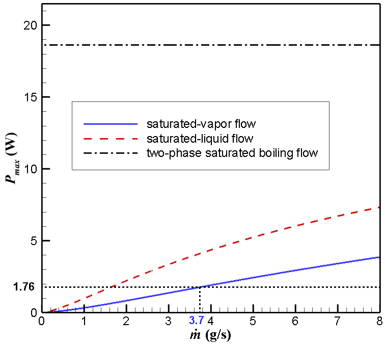
Figure 4. The predicted maximum power generation rate for the TEG waste cold recovery system with four single-layer TEG modules versus the mass flow rate
Figure 5. The heat transfer rates of the nitrogen flow versus the mass flow rate with and without the TEG waste cold recovery system
Experimental results and discussion
The TEG waste cold recovery system with four single-layer TEG modules was tested at various mass flow rates. Figure 6 shows the measured power generation rate against the electric load compared with the model predictions. As shown, only approximately one-third of the predicted power generation rate based on the saturated-vapor flow was obtained in the measurements. In reality, the nitrogen passing through the TEG system may not be saturated but very possibly overheated. In addition, the nitrogen is so cold that water in the air freezes outside the system, as shown in Figure 1. The icing layer creates additional thermal resistance. Both cause an underestimation of the thermal resistance 1/Ki. Alternatively, we determined the best values of 1/Ki based on the least-square-error principle, and the prediction results are shown in Figure 6. In this case, the predictions agree very well with the measurements. A new system that isolates the moisture in the air is under development.
(a)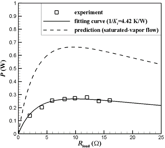 (b)
(b)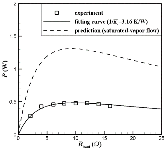
(c)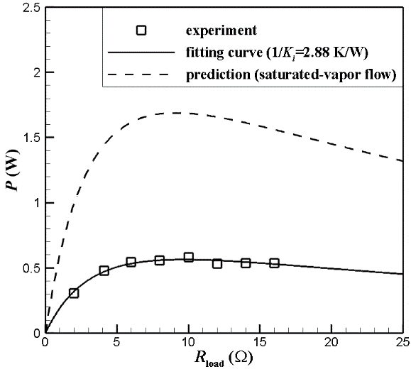 (d)
(d)
Figure 6. The measured power generation rates from the TEG waste cold recovery system with four single-layer TEG modules plotted against the electric load and the model predictions based on the saturated-vapor flow (dash lines) and the best-fit 1/Ki values (solid lines). The mass flow rates are (a) 1.7 g/s, (b) 2.9 g/s, (c) 3.6 g/s, and (d) 4.6 g/s, respectively.
Reference
Weng, C., Lin, M., and Huang, M. (2016). A waste cold recovery from the exhausted cryogenic nitrogen by using thermoelectric power generator. Energy, 103, 385-396.
Mei-Jiau Huang
Professor, Department of Mechanical Engineering